Understanding OTDRs
by Jim Hayes and the staff at fotec
Introduction
Blindly using test instrumentation to test your fiber optic cable plant can be disastrous. While today's instruments are accurate and easy to use, they all require adequate knowledge of their operation and "quirks" to get good data. As an example, we have seen several instances where users of OTDRs (optical time domain reflectometers ) accepted the automatic results of the instruments without evaluating the displays (or perhaps not knowing how to interpret the displays.) The data was highly misleading and the consequences of the bad data was very costly. The reason was simply that the OTDR was being used outside of its normal operating parameters and the interpretation of the display is critical to understanding what is happening in the cable plant.
In this article, we will examine the OTDR in detail and show examples of good and bad data. Then we will try to give you guidelines of using them. Fotec has been making fiber optic test instruments for over 15 years, we understand OTDRs. We have been involved in evaluating their performance and measurement uncertainty as part of standards activities for years, trying to understand why OTDRs and insertion loss tests give different answers. That is information we will share with you too.
If you are going to use an OTDR, read the manually
thoroughly - until you understand it fully. That will help you operate the unit
properly. Much of the information here is not included in the manual, which
generally only tells you which button to push. This article will help you
understand how the instrument works, how to interpret what it is measuring and
keep you from being misled by it.
When Do You Use OTDRs?
We bring various OTDR manufacturers to Fiber U to teach their use. Since most of our attendees are contractors, we try to give them a realistic overview of what jobs they will see and what tools they will need. It is very important to understand when you need an OTDR and when it is not appropriate.
If you are installing an outside plant network such as a long distance network or a long campus LAN with splices between cables, you will want an OTDR to check if the fibers and splices are good. The OTDR can see the splice after it is made and confirm it's performance. It can also find stress problems in the cables caused by improper handling during installation. If you are doing restoration after a cable cut, the OTDR will help find the location of cut and help confirm the quality of temporary and permanent splices to restore operation. On singlemode fibers where connector reflections are a concern, the OTDR will pinpoint bad connectors easily.
OTDRs should not be used to measure cable plant loss. That is the job of the source and power meter, which duplicates the actual fiber optic link, as we described in the first part of this article and is documented by every standard ever written for cable plant loss. The loss measured will not correlate between the two methods; the OTDR cannot show the actual cable plant loss that the system will see.
The limited distance resolution of the OTDR makes it very hard to use in a LAN or building environment, where cables are usually only a few hundred feet long. The OTDR has a great deal of difficulty resolving features in the short cables of a LAN and is more often than not simply confusing to the user.
And one OTDR manufacturer once told one of our Fiber U classes that they could justify the cost of an OTDR simply by using it to test the length of the fiber on a reel when they get it to make sure they got what they paid for. The class laughed at the instructor and pointed out the cable manufacturers mark length on the cable jacket and a $2 calculator would do as well!
Since OTDRs are very expensive and have only specific uses,
the decision to buy one must be made carefully. For that reason, most instrument
rental companies will rent one for a few days or weeks when you need them.
However, if you are not familiar with their operation or cannot understand the
results of OTDR tests, it would be much better to hire a specialist to do the
testing for you.
How Does an OTDR work?
Unlike sources and power meters which measure the loss of the fiber optic cable plant directly, the OTDR works indirectly. The source and meter duplicate the transmitter and receiver of the fiber optic transmission link, so the measurement correlates well with actual system loss. The OTDR, however, uses a unique phenomena of fiber to imply loss.
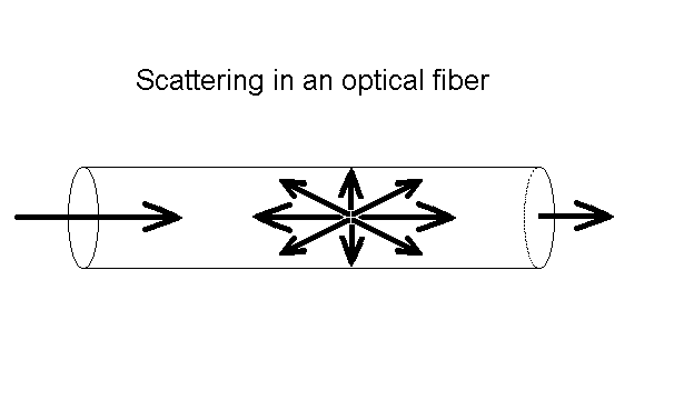
The biggest factor in optical fiber loss is scattering. It is like billiard balls bouncing off each other, but occurs on an atomic level between photons (particles of light) and atoms or molecules. If you have ever noticed the beam of a flashlight shining through foggy or smokey air, you have seen scattering. Scattering is very sensitive to the color of the light, so as the wavelength of the light gets longer, toward the red end of the spectrum, the scattering gets less. Very much less in fact, by a factor of the wavelength to the fourth power - that's squared-squared. Double the wavelength and you cut the scattering by sixteen times!

In the fiber, light is scattered in all directions,
including back toward the source as shown in Figure 1. The OTDR uses this
"backscattered light" to make its measurements. It sends out a very high power
pulse and measures the light coming back. At any point in time, the light the
OTDR sees is the light scattered from the pulse passing through a region of the
fiber. Think of the OTDR pulse as being a "virtual source" that is testing all
the fiber between itself and the OTDR as it moves down the fiber. Since it is
possible to calibrate the speed of the pulse as it passes down the fiber, the
OTDR can correlate what it sees in backscattered light with an actual location
in the fiber. Thus it can create a display of the amount of backscattered light
at any point in the fiber, Figure 2.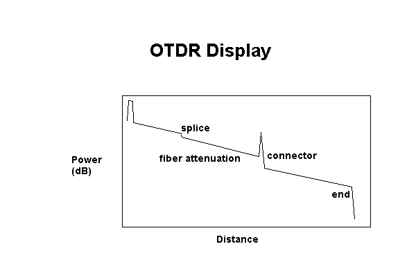
There are some calculations involved. Remember the light has to go out and come back, so you have to factor that into the time calculations, cutting the time in half and the loss calculations, since the light sees loss both ways. The power loss is a logarithmic function, so the power is measured in dB.
The amount of light scattered back to the OTDR is
proportional to the backscatter of the fiber, peak power of the OTDR test pulse
and the length of the pulse sent out. If you need more backscattered light to
get good measurements, you can increase the pulse peak power or pulse width as
shown in Figure 3.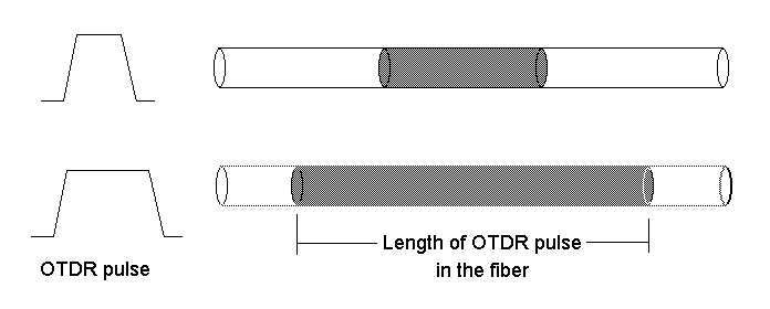
Note on the display shown in Figure 2, some events like
connectors show a big pulse above the backscatter trace. That is a reflection
from a connector, splice or the end of the fiber. They can be used to mark
distances or even calculate the "back reflection" of connectors or splices,
another parameter we want to test in singlemode systems.
Information in the OTDR Trace
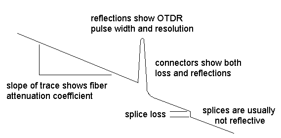
The slope of the fiber trace shows the attenuation coefficient of the fiber and is calibrated in dB/km by the OTDR. In order to measure fiber attenuation, you need a fairly long length of fiber with no distortions on either end from the OTDR resolution or overloading due to large reflections. If the fiber looks nonlinear at either end, especially near a reflective event like a connector, avoid that section when measuring loss.
Connectors and splices are called "events" in OTDR jargon. Both should show a loss, but connectors and mechanical splices will also show a reflective peak. The height of that peak will indicate the amount of reflection at the event, unless it is so large that it saturates the OTDR receiver. Then peak will have a flat top and tail on the far end, indicating the receiver was overloaded.
Sometimes, the loss of a good fusion splice will be too small to be seen by the OTDR. That's good for the system but can be confusing to the operator. It is very important to know the lengths of all fibers in the network, so you know where to look for events and won't get confused when unusual events show up (like ghosts, we'll describe below.)
Reflective pulses can show you the resolution of the OTDR.
You cannot see two events closer than is allowed by the pulse width. Generally
longer pulse widths are used to be able to see farther along the cable plant and
narrower pulses are used when high resolution is needed, although it limits the
distance the OTDR can see.
Understanding the Physics (and Errors) of the Measurement
Don't let the title put you off, it's pretty basic. The
amount of light scattered back to the OTDR for measurement is quite small, about
one-millionth of what is in the test pulse, and it is not necessarily constant.
This affects the operation and accuracy of OTDR measurements.
Overload Recovery
Since so little of the light comes back to the OTDR for analysis, the OTDR receiver circuit must be very sensitive. That means that big reflections, which may be one percent of the outgoing signal, will saturate the receiver, or overload it. Once saturated, the receiver requires some time to recover, and until it does, the trace is unreliable for measurement as shown in Figure 5.
The most common place you see this as a problem is caused by
the connector on the OTDR itself. The reflection causes an overload which can
take the equivalent of 50 meters to one kilometer (170 to 3000 feet) to recover
fully, depending on the OTDR design, wavelength and magnitude of the reflection.
It is usually called the "Dead Zone". For this reason, most OTDR manuals suggest
using a "pulse suppresser" cable, which doesn't suppress pulses, but simply
gives the OTDR time to recuperate before you start looking at the fiber in the
cable plant you want to test. They should be called "launch" cables.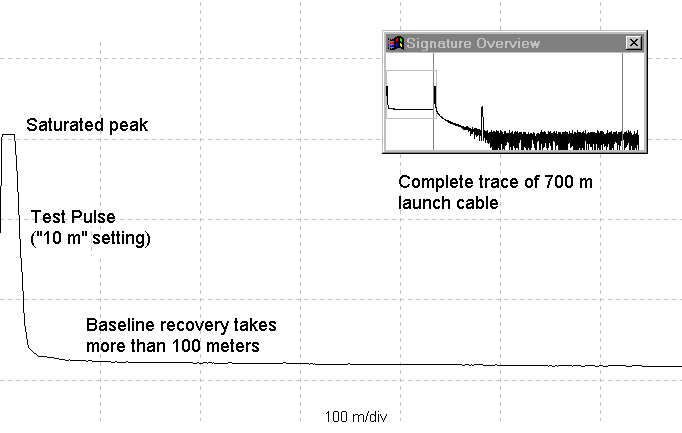
Do not ever use an OTDR without this launch
cable! You always want to see the beginning of the
cable plant and you cannot do it without a launch cable. It allows the OTDR to
settle down properly and gives you a chance to see the condition of the initial
connector on the cable plant. It should be long, at least 500 to 1000 meters to
be safe, and the connectors on it should be the best possible to reduce
reflections. They must also match the connectors being tested, if they use any
special polish techniques.
Ghosts
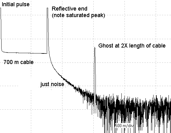
On very short cables, multiple reflections can really
confuse you! We once saw a cable that was tested with an OTDR and deemed bad
because it was broken in the middle. In fact it was very short and the ghosted
image made it look like a cable with a break in the middle. The tester had not
looked at the distance scale or he would have noted the "break" was at 40 meters
and the cable was only 40 meters long. The ghost at 80 meters looked like the
end of the cable to him!
Backscatter Variability Errors
Another problem that occurs is a function of the backscatter coefficient, a big term which simply means the amount of light from the outgoing test pulse that is scattered back toward the OTDR. The OTDR looks at the returning signal and calculates loss based on the declining amount of light it sees coming back.
Only about one-millionth of the light is scattered back for measurement, and that amount is not a constant. The backscattered light is a function of the attenuation of the fiber and the diameter of the core of the fiber. Higher attenuation fiber has more attenuation because the glass in it scatters more light. If you look at two different fibers connected together in an OTDR and try to measure splice or connector loss, you have a major source of error, the difference in backscattering from each fiber.
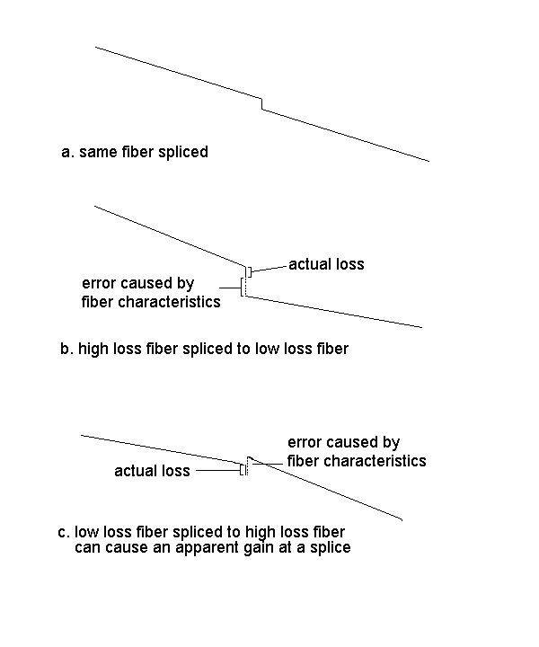
However, if the fibers are different, the backscatter coefficients will cause a different percentage of light to be sent back to the OTDR. If the first fiber has more loss than the one after the connection, the percentage of light from the OTDR test pulse will go down, so the measured loss on the OTDR will include the actual loss plus a loss error caused by the lower backscatter level, making the displayed loss greater than it actually is.
Looking the opposite way, from a low loss fiber to a high loss fiber, we find the backscatter goes up, making the measured loss less than it actually is. In fact, this often shows a "gainer", a major confusion to new OTDR users.
The difference in backscatter can be a major source of error. A difference in attenuation of 0.1 dB per km in the two fibers can lead to a splice loss error of 0.25 dB! While this error source is always present, it can be practically eliminated by taking readings both ways and averaging the measurements, and many OTDRs have this programmed in their measurement routines. This is the only way to test inline splices for loss and get accurate results.
Another common error can come from backscatter changes
caused by variations in fiber diameter. A variation in diameter of 1% can cause
a 0.1 dB variation in backscatter. This can cause tapered fibers to show higher
attenuation in one direction, or we have in the past seen fiber with "waves" in
the OTDR trace caused by manufacturing variations in the fiber
diameter.
Overcoming Backscatter Errors
One can overcome these variations in backscatter by
measuring with the OTDR in both directions and averaging the losses. The errors
in each direction cancel out, and the average value is close to the true value
of the splice or connector loss. Although this invalidates the main selling
point of the OTDR, that it can measure fiber from only one end, you can't change
the laws of physics.
Resolution Limitations
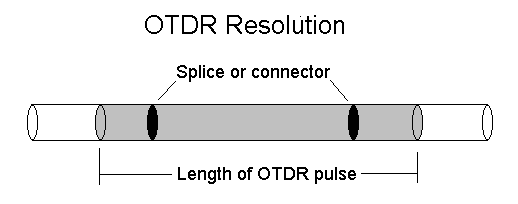
The next thing you must understand is OTDR resolution. The OTDR test pulse, Figure 8, has a long length in the fiber, typically 5 to 500 meters long (17 to 1700 feet). It cannot see features in the cable plant closer together than that, since the pulse will be going through both simultaneously. This has always been a problem with LANs or any cable plant with patchcords, as they disappear into the OTDR resolution. Thus two events close together can be measured as a single event, for example a connector that has a high loss stress bend near it will show up on the OTDR as one event with a total loss of both events. While it may lead you to think the connector is bad and try to replace it, the actual problem will remain.
There is a tool that will help here. It is called a "visual fault locator". It injects a bright red laser light into the fiber to find faults. If there is a high loss, such as a bad splice, connector or tight bend stressing the fiber, the light lost may be visible to the naked eye. This will find events close to the OTDR or close to another event that are not resolvable to the OTDR. It's limitation is distance too, it only works over a range of about 2.5 miles or 4 km.
The visual fault locator is so valuable a tool that many
OTDRs now have one built into them. If you are using an OTDR, you must have one
to use it effectively.
Special Consideration for Multimode Fiber
Most OTDR measurements are made with singlemode fiber, since most outside plant cable is singlemode. But building and campus cabling are usually multimode fiber using light emitting diode sources for low and medium speed networks. The OTDR has problems with multimode fiber, since it uses a laser source to get the high power necessary to cause high enough backscatter levels to measure.
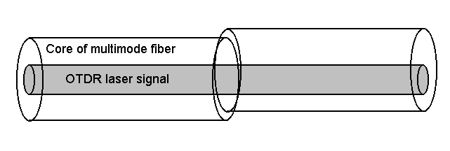
Figure 9. OTDRs only see the middle of the multimode fiber
core
Several projects have tried to determine how to corellate
OTDR measurements to source and power meter measurements, without success. Our
experience is an OTDR will measure 6-7 dB of loss for a multimode cable plant
that tests at 10 dB with a source and power meter.
Measuring Fiber, not Cable Distance
And finally, OTDRs measure fiber not cable length. While
this may sound obvious, it causes a lot of problems in buried cable. You see, to
prevent stress on the fiber, cable manufacturers put about 1% more fiber in the
cable than the length of the cable itself, to allow for some "stretch." If you
measure with the OTDR at 1000 meters(3300 feet), the actual cable length is
about 990 meters (3270 feet). If you are looking for a spot where the rats
chewed through your cable, you could be digging 10 meters (33 feet) from the
actual location!
Examples of How to Use the OTDR and Avoid Errors
Here are some actual examples of how to use an OTDR properly
(and improperly) and some tricks to overcome some of the problems you encounter.
The most adamant advice we will give is this: Do not blindly accept the data
without interpretation. Most of today's OTDRs have "automatic modes" where they
will find splices and connectors and calculate all the losses, if the data
follows preprogrammed guidelines. In our experience, these numbers are not
to be used without human interpretation of the results, as the OTDR is basically
a PC, isn't too smart, and the software has limitations if the cable plant has
high reflections or short cable runs.
What Does a Good OTDR Trace Look Like?
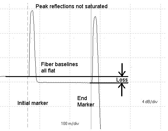
Setting the markers slightly away from the event won't affect the loss measurement by adding significant fiber loss. Remember fiber loss is only 0.01 dB per 10 meters (33 feet) at 1300 nm! By going further from the event, you reduce the possibility that the measurement is in error because of instrument limitations.
If the trace never shows a straight line between events,
like Figure 5, it means either the distance between events is too short for the
OTDR resolution or reflections are too high for the recovery time needed before
the next event. In this case, you cannot get good data on either fiber loss or
event loss.
This "Trick" Can Help
There is a trick you can try if you are desperate. The reflection at an event that causes overloading the OTDR receiver can be tamed by using "index matching fluid" to reduce the effect that causes the reflection. The reflection is caused by an air gap between the ends of the fibers. Connectors are particularly bad at having this air gap and resulting high reflections. An index matching fluid replaces the air with a fluid or gel that closely matches the optical characteristics of the glass, causing the reflections to be greatly diminished.
Figure 11 two traces of the same fiber. It is only 700 feet or 200 meters long, which is normally considered quite short for OTDR analysis. The intial trace shows the connector on the OTDR end has high reflections, saturating the OTDR and causing the baseline of the trace to decay slowly. Even the second pulse, from the connector at the far end of the cable has very high reflections. Both reflections caused ghosts also.
Since the baseline between the two ends never becomes flat or straight, there is no reliable reference point for making a loss measurement.
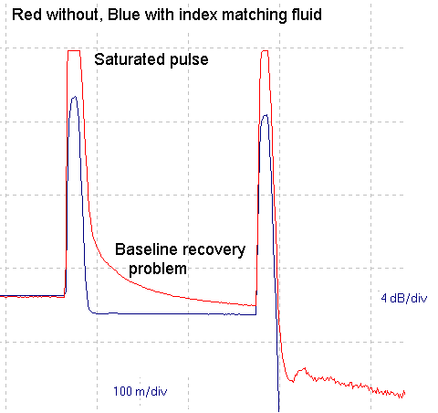
Index matching fluid can be purchased from a specialty fiber optic distributor or from your local supermarket or druggist. The special fluids work very well but are expensive. Mineral oil or plain petroleum jelly work almost as well! If you can get silicone "high vacuum grease", it works very well too.
Using this technique gives us visibility we would never have
otherwise, but the technique requires care. The index matching fluid or gel must
be thoroughly cleaned from the connectors after use with the OTDR. The splice
bushing used must not be one in the network hardware, but a separate item that
can be used and discarded or thoroughly cleaned in solvent afterwards. Index
matching fluid or gel will act like a magnet for dirt if it gets on any hardware
or stays on the connectors, as its sticky texture will grab and hold lots of
airborne dirt to attenuate the signal in the fiber link.
Summary
Testing fiber optic cable plants are easy if you have the
right instruments and follow industry testing standards. When diagnosing
problems, you must be creative to develop techniques that help reveal problems
that show up on standard tests. It is most important to know your tools
operation and limitations, and how to work around them. Get to know the
applications support staff at your instrument vendor so you can call with
questions. Finally, it is most helpful to have good cable plant documentation,
since knowing what you are looking at will make it much easier to find
problems.
We'd like to thank the applications and marketing people at Photon Kinetics for the loan of a PK7500 mini OTDR and PC7510 software to gather and analyze some of this data.
Enhance your fiber optic knowledge with Fiber U Online